I haven't really officially introduced myself here yet. My name is Jason and I have a 1st gen II(that feels like the introduction to an addiction meeting). I originally planned on building a drag car but have since decided I want to go road racing.
I spent some time yesterday setting up the rear suspension. Nothing is welded in yet and I need to fab some brackets for the lower links to connect at the cross member. I am mainly waiting on my bushings to do this.
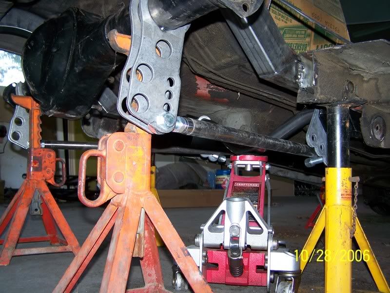
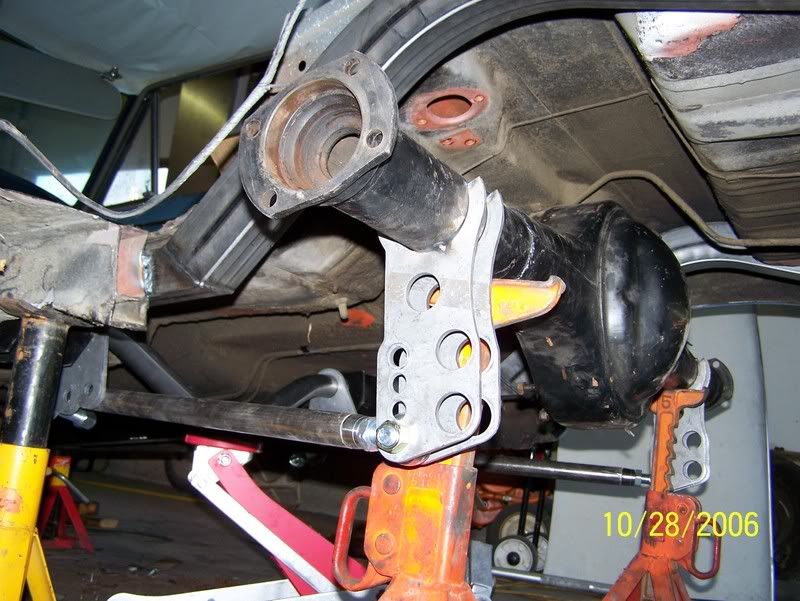
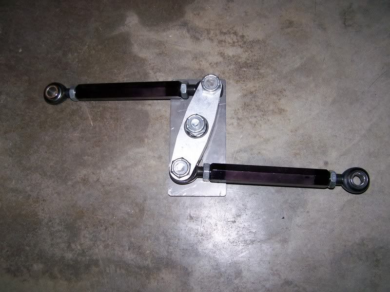
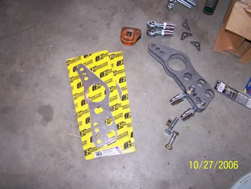
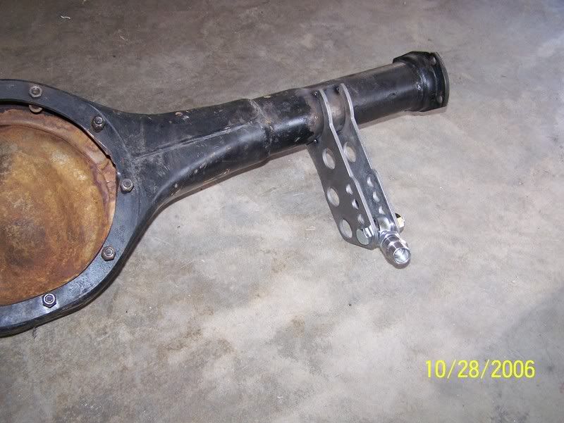
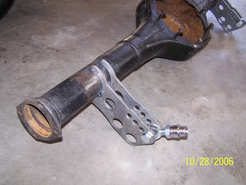
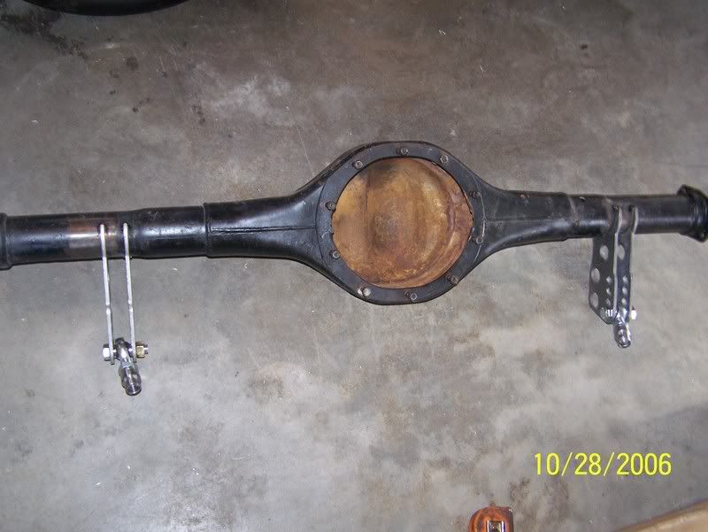
Here are the brackets for the axle housing. All I needed was the lower portion so I cut the tops off. I am going 3-link with a watts link.
![Image]()
![Image]()
![Image]()
![Image]()
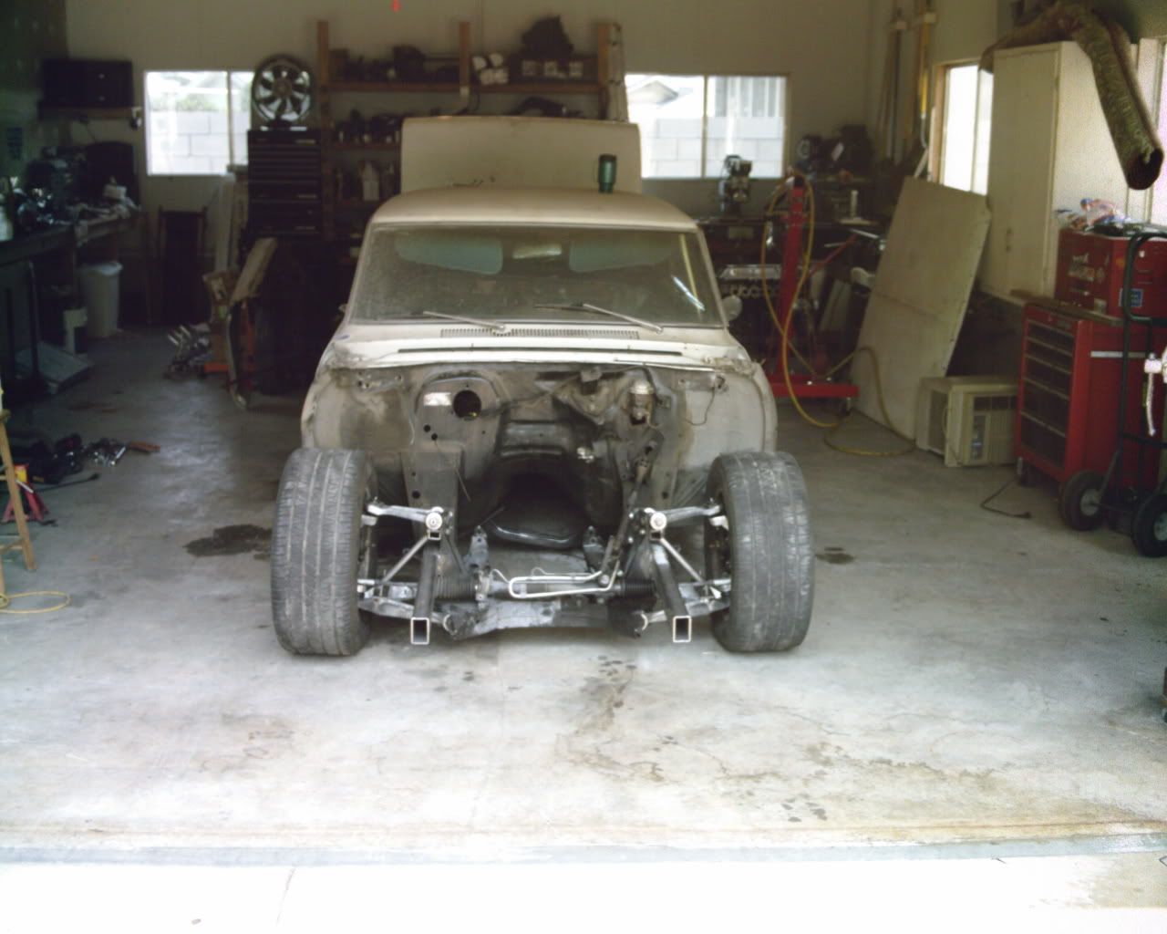
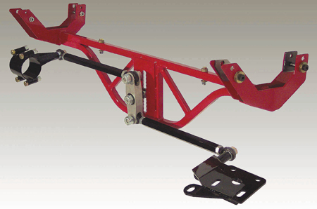
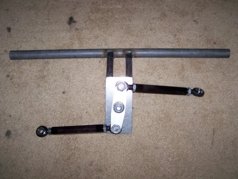
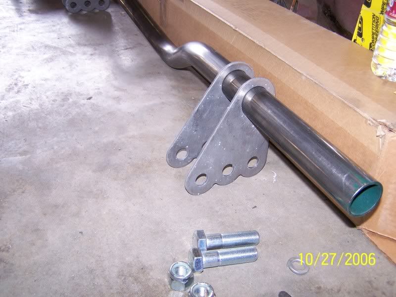
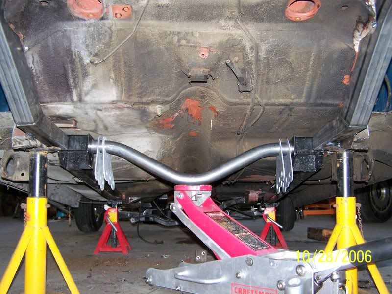
Here is the CE front ladder bar style cross member.
![Image]()
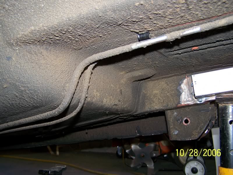
Here is what the frame looked like before. (notice the new CE rear frame rails already in place). I moved these rails inboard of the stock rails to gain wheel clearance. I am hoping to run 12" wide wheels with a 335 tire.
![Image]()
![Image]()
![Image]()
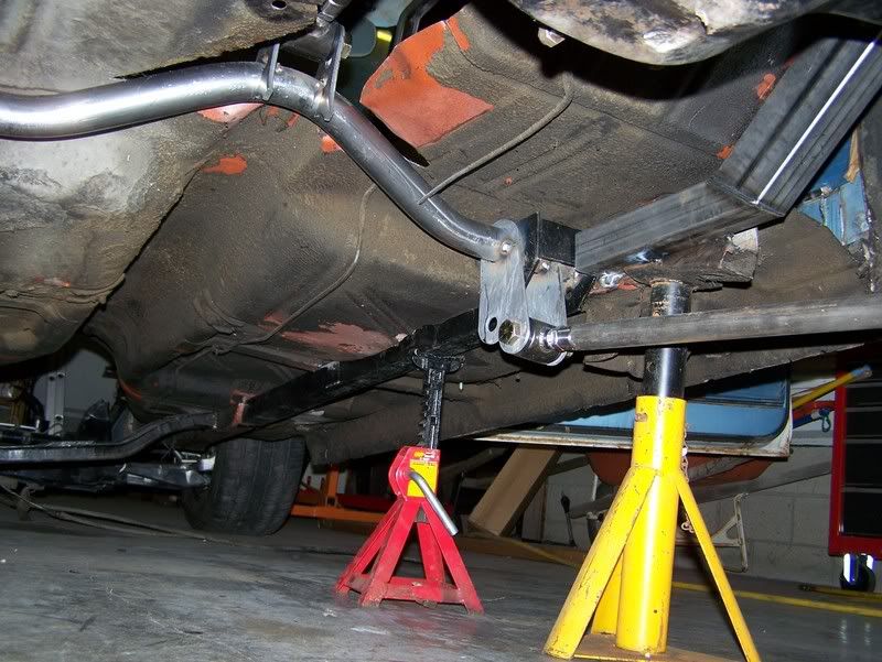
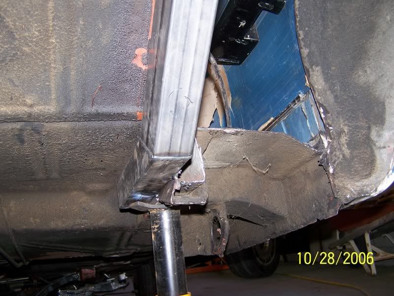
Here the crossmember and CE subframe connectors are in place. I had to cut the floor slightly to fit the subframe connectors in this position. I switched the connectors from side to side so they would go inboard of the frame rails instead of to the bucket.
![Image]()
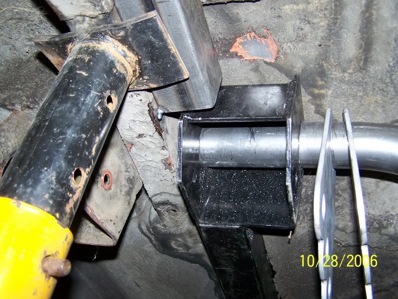
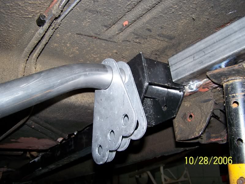
Here you can see where I had to drill a hole in the subframe connector to slide the cross member into. Also notice the brackets just hanging there. These will be changed in time I just needed something to hook the links to for moch up.
![Image]()
![Image]()
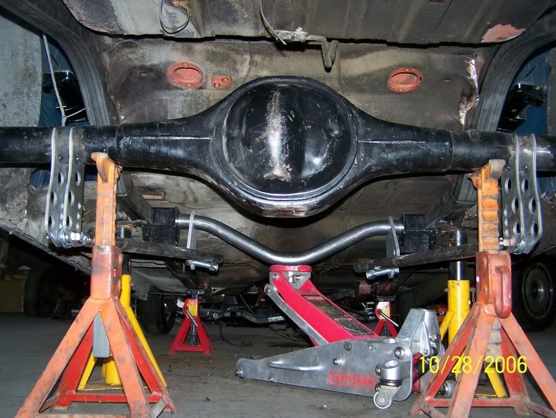
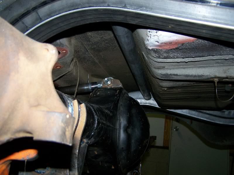
Last but not least the rearend in place and the lower links jurry rigged to the front brackets.
![Image]()
![Image]()
![Image]()
I spent some time yesterday setting up the rear suspension. Nothing is welded in yet and I need to fab some brackets for the lower links to connect at the cross member. I am mainly waiting on my bushings to do this.
Here are the brackets for the axle housing. All I needed was the lower portion so I cut the tops off. I am going 3-link with a watts link.
Here is the CE front ladder bar style cross member.
Here is what the frame looked like before. (notice the new CE rear frame rails already in place). I moved these rails inboard of the stock rails to gain wheel clearance. I am hoping to run 12" wide wheels with a 335 tire.
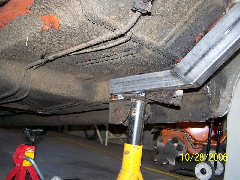
Here the crossmember and CE subframe connectors are in place. I had to cut the floor slightly to fit the subframe connectors in this position. I switched the connectors from side to side so they would go inboard of the frame rails instead of to the bucket.
Here you can see where I had to drill a hole in the subframe connector to slide the cross member into. Also notice the brackets just hanging there. These will be changed in time I just needed something to hook the links to for moch up.
Last but not least the rearend in place and the lower links jurry rigged to the front brackets.