Chevy Nova Forum banner

Leaf Spring Help

22K views 38 replies 11 participants last post by  mnadams2  
#1 · (Edited)
Hello all. About 10 months ago, i purchased a 73 pro-streeted hatchback nova rolling chassis. I finally drove it around town last night, and noticed that when i hit bumps, there is a violent sound in the rear-end like the frame is bottoming out. On the way home, one bump actually completely knocked my rear window out of the hatch, but i was able to stop slowly and recover it without it sliding into the road. Its tubbed in the rear and it sits so low that the frame sits only 1" above the leafs when on a level surface. Im sure that i will need to cut the shackles and put a 1"-2" block to space the leafs further down away from the tubular frame, right?

I would like to purchase this suspension kit from Hotchkis this week: http://www.summitracing.com/parts/HSS-80013/ All bushings are worn out in the front and rear, and the car didnt come with a sway bar. But looking at the leafs today, they sure do seem long. Is it possible that the leaf springs' are from another car due to the tubbed rear end, and if i buy this kit, the springs wont work? Can anybody give my a center-to-center distance of some leaf springs that will fit my car? Any advice on the bottoming out situation would be appreciated too. Thanks guys.
 
#4 ·
pics

here is the link to a few pics. yes, im wanting to put it on the street. if i have to 4 link, i will. but i figured i would get some advice to see if there is a quick fix. i have experience with welding and fabrication, just need to be pointed in the right direction. i measured the length of the springs from center to center, and the length is consistent with the oem length for leaf springs for a 73 nova: 56". thanks.

Image


Image


Image


Image
 
#5 · (Edited)
4 link

Ok, after reading through all the forums, ive decided to do 4-link and watts links. however, the car sits so low that i wouldnt have anywhere to mount the top links b/c the tube fram that loops up and over the axle is only like 3 inches away from my rearend. i could raise the car up, but i would have to raise it up like 6 inches to make a difference. even then, 3 inch long control arm? i know if missing something here, but how do i go about locating the mounting points on my frame. i would assume that i would run the bottom links somewhat parallel along the tubular frame rails, just not sure about the top ones. id like to purchase a kit similar to this one: http://www.summitracing.com/parts/CEE-2028/ im thinking something like this may work, with the upper links very short : http://i1017.photobucket.com/albums/af298/mnadams2/nova%20rearend%20problem/4_link_option1.jpg I have a 9" ford with 31x15.5 tires. (i like big tires)
 
#6 ·
I have the Hotchkis springs and sway bars. It is very nice, but it is a pro-touring/road racing setup. It is very firm. If you are looking for a pro-street ride or something more comfortable, I'd look else where. Your current springs look like someone took a couple of leafs out of a 5 leaf stack.
 
#8 ·
pro-touring

tnblkc230wz,
I would like to set the car up to handle corners. I would love to do the Hotchikis pro-touring setup, but im concerned about the current leaf spring mounts under the frame b/c of the bottoming out issue. the reason that there were a couple of leafs taken out, im sure, is to drop the car down a little lower. is your car tubbed in the rear? im just not so sure about using leaf springs without raising the car up and getting rid of the killer stance the car has. thanks.
 
#10 ·
unorthodox 4 link configuration

with the little room that i have in between my rear end housing and my frame, i have an idea. could i put my bottom links going towards the front of the car (like a normal 4 link setup), but put my top links going towards the back of the car? ias long as the top and bottom links are moving equal and opposite, but changing vertically at the same rate, this should be possible. i use mechanical design CAD software at work, and could draw it up to find the mounting locations, but just wanted to get another opinion. has anybody ever seen a f 4 link setup like this?
 
#11 ·
bottoming out

Remove the 3'' lowering blocks, All they do is pull your suspension down tight,
Get yourself some new shorter u bolts and your car will ride fine, it might sit up higher in the rear, But your ride will be alot smoother.My dad had them on his car and it rode like a tank. try it, it's cheap to do..
 
#12 ·
You removed a leaf which made your spring hit the frame. You need to reinstall the spring to get away from the frame or replace them. Due to that frame design the only way to lower it with leafs is using blocks. tall springs for frame clearance and blocks to get it back down. No choice other than modifying the frame where the right angle is or go to coil overs. :yes:
 
#13 ·
4 link

ive decided to "fix" the right angle frame problem. i have ordered the following kit from summit: http://www.summitracing.com/parts/CEE-3060/ ill just cut out the tigh right angle and weld these in. that will give me more clearance in the front of the axle housing to put 4 links. ill have to rework my sheetmetal, but i think i will be more please than i am with the current geometry.
 
#14 · (Edited)
4-Link

Ok, here it is. The first thing i did is jack the car up the same amount on each corner and rearend housing (about 12") and put jackstands under the car, to ensure that all the work i would be doing would be at ride height. Then i unbolted the leaf springs from the perches, and cut the perches off the the frame and rearend housing.

Since the existing 9" Ford housing was already narrowed for big tires, i had to cut the 4-link brackets in half and tack the 2 halves to the rearend axle tubes at the same width as the existing sub-frame connectors; and b/c my axle tube diameter was larger than the 4-link bracket holes, i had to enlarge them. Also, i welded them to the housing so that the yoke was centered with the tranny output shaft.
Image


Then i welded the frame rail assembly together outside of the car to ensure it was square. (http://www.summitracing.com/parts/CEE-3060/).

The existing subframe connectors were simply 2x3 tubing welded to the front clip; so i left the rearend in place, and measured the tubes that came with the Competition Engineering 4-Link kit (http://www.summitracing.com/parts/CEE-2017/) and hiems (http://www.summitracing.com/parts/CEE-6162/) & (http://www.summitracing.com/parts/CEE-6163/), and just cut the sub-frame connectors. Before cutting, i dropped several plumb-bobs to make sure that the rearend was square in the car. For the measurement on where to cut the sub frame connectors:
*i measured the eye-to-eye length of an assembled a 4-link bar (heim-tube-heim) with the heims threaded halfway in
*then i added the 3" to compensate for the frame rail weldment (which is 2x3)
*then added the measurement of "the middle 4-link rearend bracket hole to the middle of the axle tube"
*then i added the mesurement of "the middle 4-link frame bracket hole to the edge of the bracket"
Image


Then i welded the frame rail assembly to the subframe connectors, and to the rear of the car. I then welded a dropped crossmember at the joint to tie the subframe-connectors and frame rail assembly together. http://www.summitracing.com/parts/CEE-3061/ I also welded another drop crossmember in between the subframe connectors at the point where they weld to my front clip (about 10" behind the tranny output shaft). I then purchased a 1x2 drive shaft loop and welded the halves on top of each dropped crossmember; i called and asked Checkered Racing (great guys!) to just send me the 2 halves unwelded. http://stores.checkeredracing.com/Detail.bok?no=27 I also purchased/installed Competition Engineering's Diagonal link kit. http://www.summitracing.com/parts/CEE-2052/
Image


Image


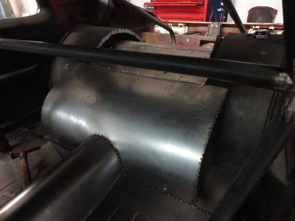
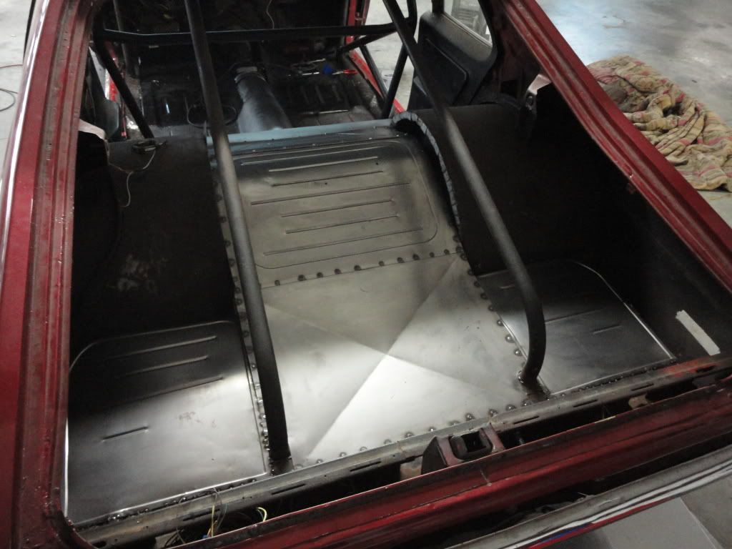
Then i bolted in a new floor pan support. http://www.summitracing.com/parts/GMK-4012-517-681/
Image


I also welded patches over any small holes (rust) in the rocker panel and sanded smooth.
Image


Image


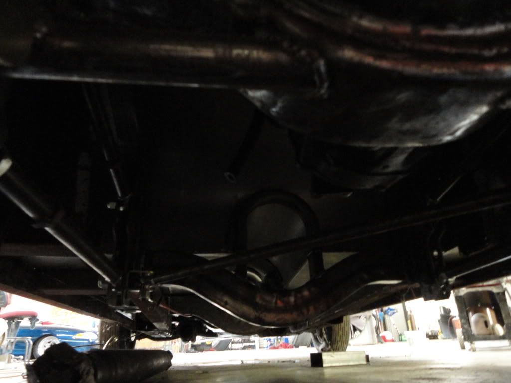
Next, i tacked the shock mount brackets from QA1's Shock Mount Kit in place in a way that my coilovers were perpendicular to the ground, and as wide as i could make them. http://www.summitracing.com/parts/HAL-MT100K/ Then pulled the rear end out, and hard-welded everything. I also welded 1.25"O.D., 1/8"wall through the 4-link brackets, through the shock brackets, and into the side of the rear end housing to tie it all together.
Image


Image


Image


I also used a hole saw bit to cut a hole in the frame rails for the bushings in Competition Engineering's Anti-Roll Kit (
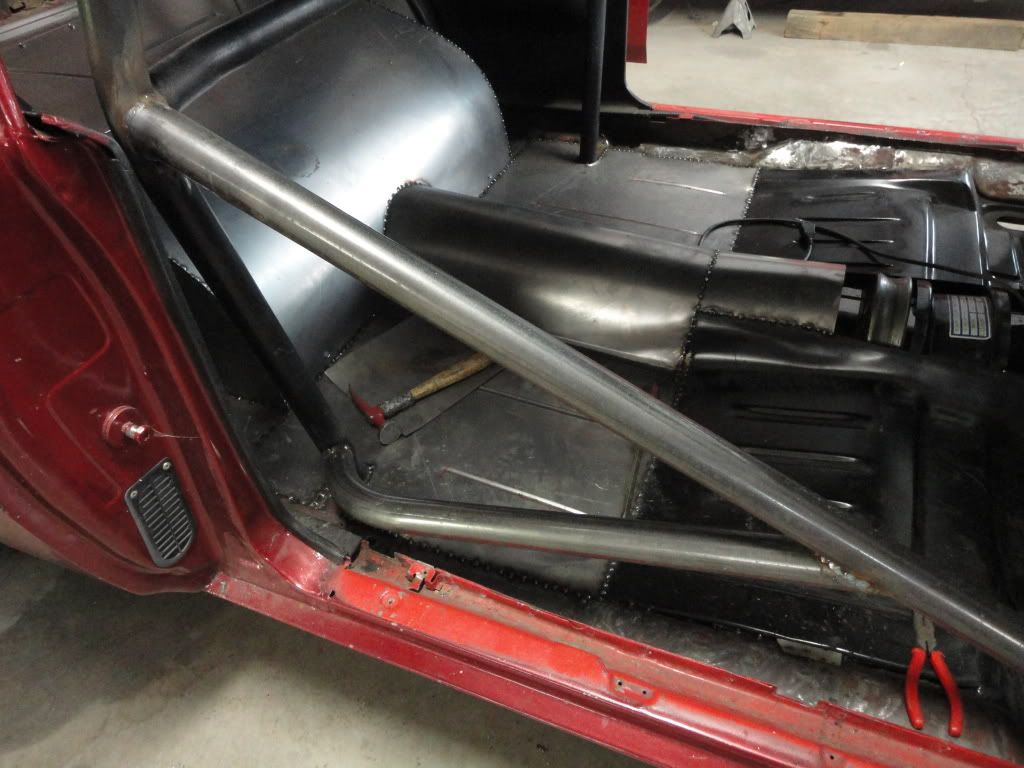
http://www.summitracing.com/parts/CEE-2041/). I am waiting untill the car is completely finished and all weight has been added until i weld the anti-roll brackets to the rear-end housing. Currently, the floor pan is 95% finished (all that lacks is the tunnel). I bought the LH/RH floor pans and cut them where they started to dip down and touch the subframe connectors (which would be the part that starts to angle down towards the back where the rear passengers' feet would be). http://www.summitracing.com/parts/GMK-4012-500-68L/ http://www.summitracing.com/parts/GMK-4012-500-68R/ The rollcage is the current task. Both rollcage and floor pan courtesy of renowned drag racer Sonny Smart of Tellico Plains, Tennessee.
Image


Image


Image


Image


Image


Image


Image
 
#15 ·
Diagonal Link

Does anybody have the same diagonal link kit that i installed here? the diagonal link is only about 1" below the driveshaft. so if i hit a bump, then the diagonal link will hit the driveshaft. somebody told me one time that they had to put a bend in the diagonal link to give them more room between the link and drive shaft. ?????
 
#16 ·
Progress...

Rear of car welded, sanded, and painted:

Image


Rearend welded, sanded, and painted:

Image


Floor pans and roll cage welded, sealed, and painted.:

Image


Rear floor and cage:

Image


Driver and passenger seat mounts (welded to frame cross-bracing underneath and to floor):

Image
 
#18 · (Edited)
front mount rack and removeable crossmember

ive decided to do a front crossmember and rack configuration similar to this one i found on s&w's website:

http://www.swracecars.com/Files/35-371 Instructions.pdf


the difference is that im going to leave provisions for the factory engine mounts. so i had to weld in a triangular 1/8" plate to fill in the hole left when trimming back the factory crossmember. heres where im at so far:

*heres what i cut out using a sawzall and cutoff wheel on 4 1/2" angle grinder:
Image


*i welded in 1.5" x .120 DOM in place of the front crossmember.
*drivers side front crossmember mount:
Image


*passenger side front crossmember mount:
Image


*drivers side rear crossmember mount:
Image


*passenger side rear crossmember mount:
Image


*underside shot:
Image


next step is to weld in the 1" x .120" DOM diagonals w/ mounting tabs for the removable crossmember
 
#20 · (Edited)
i have been looking at this one from Summit:
http://www.summitracing.com/parts/SUM-770604/

But for now, Dad has one he is going to loan me. I may have to modify it to fit, and if i do, i may end up having to buy one so i dont have to molest his.


I got the diagonals tack welded in tonight. the rack will sit almost on top of the diagonals. Both diagonals are level to the ground and front 1.5" crossmember, just comes in at a 50* angle.
Image


View of the passenger diagonal coming into the lower rear control arm mount:
Image


I'm also going to weld a plate on the bottom similar to this for a jacking point. Ill cut some angles in it to make it look a little nicer
Image


Next step is to weld the mounting tabs for the removable crossmember that will have clevises on each end (between the lower rear control arm mount); and then weld up the removable crossmember.

I also plan to enclose the front (where the diagonals come into the 1.5" tube) by welding a 2.5" tall plate that goes across from the end of one diagonal to the other, then welding a tow hook to the front of this plate.
 
#22 ·
90% done with the front end modification

Here is the pic of the front end with everything tacked in place:
Image


Closeup of where the removable crossmember bolts to the rearward lower control arm mount:
Image


Showing off the jacking plate that is also fully welded to tie everything together; i will also weld a tow hook to the front face:
Image


Image


These control arms just came in from ebay; they look great:

http://www.ebay.com/itm/Camaro-Tubu.../330372822867?pt=Motors_Car_Truck_Parts_Accessories&vxp=mtr&hash=item4cebc13753


I also just got this kit in from Jegs, and will install after the control arms:

http://www.jegs.com/i/JEGS+Performance+Products/555/630020/10002/-1
 
#24 · (Edited)
progress update

I purchased an aluminum 9" ford thirdmember with 4.57 motive Pro gears and a 35 spline pinion.
Image


I also had Hudlow Axle cut me some 35 spline axles with 5/8" studs:
Image


Here is the rearend assembled:
Image


And installed:
Image


I got the tubular control arms and this Jegs disc brake conversion kit installed. I use Rustoleum High Heat 2000* temp primer/black paint; i taped up and painted the rotors, spindles, brake calipers, and caliper mounting brackets:
Image


I also ordered these billet steering arms from S&W Racecars :
But, they have TRZ milled into them...
Image


I have the rack & pinion clamped in place with c-clamps, and am working this weekend on positioning it for zero bump steer. It is a mustang 2 r&p, and the tie rods were about 1" too short on either side, so i welded a fine thread coupling nut onto the end, which also gives me some flats to grab onto when adjusting toe in/out:
Image
 
#26 · (Edited)
got burned out, took a couple weeks off, im back at it now...

i took the manual rack apart and removed the rack and the pinoin and cleaned them, and put it back together. it turns easier now. i took a long piece of all thread and wrapped a shop towel around it and cleaned the bore of the rack out. here is the rack bolted onto the tabs i have welded onto the new tubular crossmembers:
Image


here is the steering linkage. i got the couplers and shaft from Summit. i tacked the shafts to the couplers while in the car, and removed it and drilled/tapped holes so the joints are removable, then grinded the welds off and sanded them down smooth. this will make it easier for installation/removal:
Image


my wife helping clean back side of wheels with pneumatic wire wheel. i had to include this. she walked outside and said "i wanna try". i couldn't get the wire wheel in her hands fast enough, lol:
Image


i bought this Competition Engineeering Wishbone Kit from Summit. I didnt have ER80S-D2 wire for the chromoly. i just used my ER70S mild steel wire and preheated each weld joint before welding. Here it is installed:
Image


And here it is with a pic of the new driveshaft and 3rd member installed:
Image
 
#30 ·
i took the manual rack apart and removed the rack and the pinoin and cleaned them, and put it back together. it turns easier now. i took a long piece of all thread and wrapped a shop towel around it and cleaned the bore of the rack out. here is the rack bolted onto the tabs i have welded onto the new tubular crossmembers:
Image


here is the steering linkage. i got the couplers and shaft from Summit. i tacked the shafts to the couplers while in the car, and removed it and drilled/tapped holes so the joints are removable, then grinded the welds off and sanded them down smooth. this will make it easier for installation/removal:
Image


my wife helping clean back side of wheels with pneumatic wire wheel. i had to include this. she walked outside and said "i wanna try". i couldn't get the wire wheel in her hands fast enough, lol:
Image


i bought this Competition Engineeering Wishbone Kit from Summit. I didnt have ER80S-D2 wire for the chromoly. i just used my ER70S mild steel wire and preheated each weld joint before welding. Here it is installed:
Image


And here it is with a pic of the new driveshaft and 3rd member installed:
Image
What is the rack out of?
 
#27 ·
tie rod design

Well, after hearing about a friend of mine having a wreck at the drag strip b/c of a broken weld on a tie rod, ive decided to redesign how ive extended mine. Its not that i dont trust my welding, but the weld becomes the weak point and with the front end possibly seeing flight time, i want to make sure when it sets back down, the tie rods dont cause any problems.

As seen in a few posts back, i welded on threaded female couplers to the end of my tie rod tubes. My plan was to just thread a male shanked rod end into this coupler. But, a stronger and more dependable design would be to screw a high strength all-thread deep into the existing threads of the tie rod tube, and simply put a female threaded rod end on the other end of the all thread. So thats what i did:

Image


I cut off a little of the threaded coupler, and left just enough to have some flats to adjust toe in/out with a wrench:
Image