The following is a breakdown of how to wire your own stand alone LSx harness. The harness is almost stand alone already, and will take very little to modify. This uses a 2000 PCM and harness for an automatic car. 1999 to 2002 all share the same pin outs and wiring, with a couple of exceptions, but nothing major. The pictures and descriptions will detail the marking, disassembly, sorting and reassembly of the harness to suit where I decided to mount the PCM. The “pigtail” is about 5-6 feet long and will allow me to mount it just about anywhere in the front of the cab.
There are several sources on the internet to get the pin outs, and wiring diagrams, two of those being Alldata.com, (which you have to pay $25.00 to access), and has the best drawings, in color, and also LT1swap.com. Don’t forget LS1tech.com either, it’s a warehouse of information on all types of swaps.
If you are not sure of wiring methods or practices, or cannot read a schematic, this is probably not for you. Although there are good diagrams, schematics and pin outs, you need a good understanding of wiring to achieve this. Once you get into it though, it will become easier to understand, and you will also understand why vendors charge so much for these; this is not for the faint of heart, but can save you from 400 to 1,000 dollars depending. I'll post up some helpful links at the end, when we are all done.
For future reference, left and right will be defined as driver’s side(bank one), and passenger side (bank two), respectively.
Part 1 – Marking, disassembly, and routing.
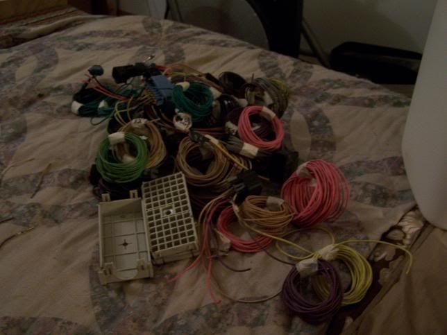
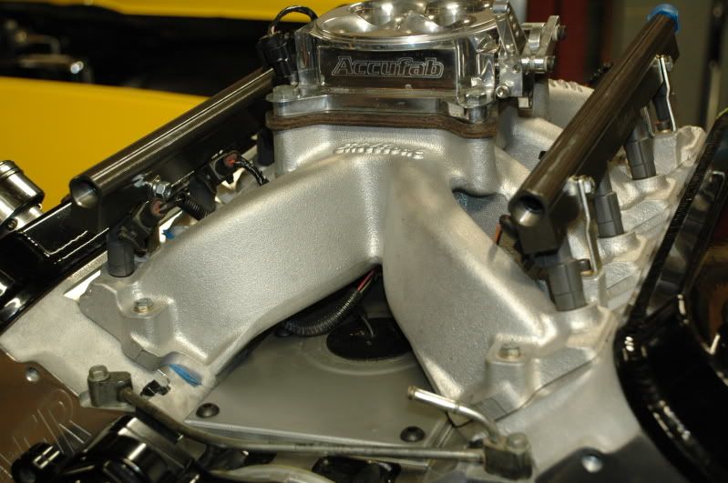
The first picture shows what you start out with. You will need to remove all the convoluted tubing, tape, tie wraps, straps and hangars to expose the wiring itself.
![Image]()
You have two connectors, red and blue, each one numbered from 1-80. Remove the red and blue caps from the connectors by inserting a small screwdriver into the slot on the end to depress the tab inward, and lift each end off the plug. Take a small wire brush and clean the numbers on each side so they are easy to read. A magnifying glass comes in handy here. Do this one at a time, AFTER you have marked the wires with color, and number. The connector color is written on the connector body, but is hard to find, and is easier just to do it one at a time. You don’t want to swap these accidentally. They only fit on the connector body one way, so you can’t reinstall them wrong, but you can get the wrong color cap on the wrong connector.
Mark each individual wire with the corresponding color of the harness connector, and then mark each wire with the correct number.
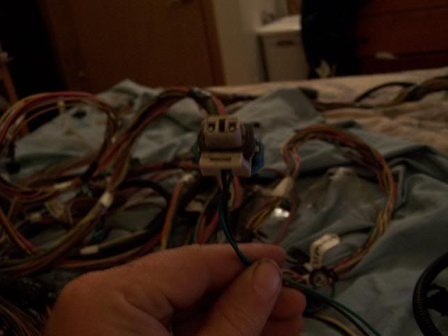
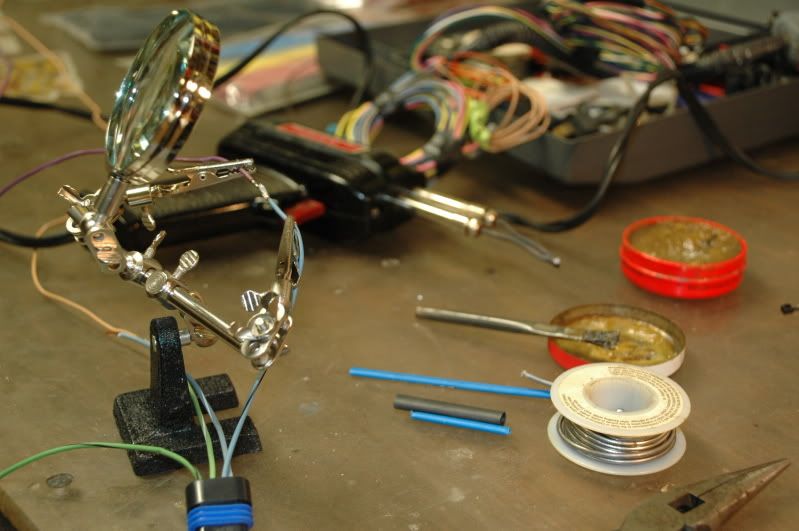
To de-pin the harness, take a small screw driver and lift the white tab away from the pin. Rock the pin outward to lift it out of the socket, and push it through the backside of the connector. What you will be left with is an amazing bird nest of wire, but don’t worry, most all of them will go back.
![Image]()
![Image]()
![Image]()
![Image]()
![Image]()
![Image]()
It is going to be most helpful if you have your engine handy with all the sensors so you can plug them all in to aid in routing the wiring. The basic idea is to identify the pink wires for ignition hot (switched), and the orange wires which are hot all the time. Refer to your wiring diagram for those wires, and their numbers, and which ones are fused with the correct size fuse. They will be easy to identify, as you can use the colors from the diagram to match up wire numbers and colors to the respective sensors. The injector connectors have numbers stamped on the inside, so they will be easy to spot, same as a small block Chevy, odd on left, even cylinders on the right.
To custom route the harness, you are going to have to cut the pink wires and the ground wires loose from the harness, but you can splice these later as you figure out your harness layout. I used a running splice, and soldered ALL joints, then used shrink tube to seal. Do not use butt connectors, as this will eventually leave you on the side of the road.
![Image]()
![Image]()
![Image]()
![Image]()
![Image]()
Some of the connectors and/or wiring are going to be deleted and are as follows:
C100, C101, C105, C220, C230. These connectors carried tachometer, speedometer, fused wires etc, to the stock instrument cluster and fuse block. These connectors and pin assignments are detailed extensively at LTswap.com. Some wires will be deleted, some reused, but the connectors themselves will be discarded for the purposes of this rewire, unless you are swapping say an LSx into a LT1 car.
Bank one, left rear O2 sensor.
Bank two, right rear O2 sensor.
Skip shift solenoid, reverse inhibit (for manual transmission)
Air pump
Fuel level sensor
Fuel tank pressure sensor
EGR Valve
Engine oil level switch (optional for warning light, you can leave this if you want a low oil light)
Evap. canister vent and purge solenoids.
Secondary air injection pump and valve.
Traction control, antilock brake system.
Cruise control.
Anti theft system.
Instrument cluster, radio.
Connectors you will need to start the engine.
MAP – manifold absolute pressure, located at the back of the manifold.
Cam position sensor, at back under to the MAP.
Knock sensors, under the intake, pigtail comes out at the back of the intake also.
Crank sensor, right side right above the starter.
Both O2’s, 4 total, but you only need two, bank one, sensor one, front, bank two, sensor one, front.
Fuel injectors-eight connectors.
Coil connectors, one each side, 4 coils right, 4 coils left bank.
IATS – intake air temp. sensor, located in air intake piping at front.
IAC – idle air control valve, large sensor on throttle body, left side, top sensor.
TPS- throttle position sensor, right below the IAC on throttle body.
ECT-engine coolant temp. Sensor, left side in head, right by #1 cylinder.
MAF-mass air flow sensor, inline in intake tubing, (most important sensor on the engine).
Alternator plug-one wire, left side at alternator.
VSS-variable speed sensor, right side of tranny, at tail shaft.
Tranny plug-multi pin connector, right side midway of tranny on top of pan.
Wires you will need to add/extend from red and blue connectors:
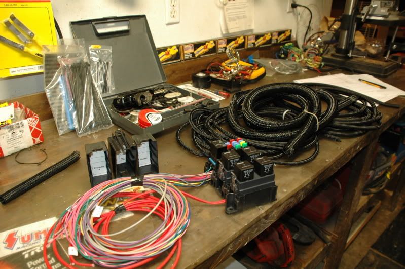
These wires were removed when you removed the five connectors to the original body harness and emission controls. The fuse sizes are on the schematic for ignition wires and the others. They will be put back, but will not go back into the connector. For the pink ignition wires, you will need an ignition relay to switch power to a small fuse block, or vice versa, your choice here. You will also need a fuel pump relay, based on the current draw of your pump. The orange wire is fused hot all the time, not controlled through any relays; this powers the PCM, and holds full time power to the PCM to maintain the program and learn cycles of the PCM.
Wires are as follows;
Tachometer output (White wire to pin #10 on the red connector, labeled tach out)
Speedometer output (Dark green/white to pin #50, on the red connector, labeled VSS out)
A/C request-connects to A/C clutch signal wire to raise idle when A/C is turned on, and also starts both fans (Dark green/white to pin #17, on the red connector, labeled A/C request)
Torque converter lockup- 12v positive signal, hot all the time, connected through brake light switch to defeat lockup when brake is pressed. Use switch from 1985 Monte Carlo with cruise control.(Purple wire to pin #33, on the blue connector, labeled TCC\Brake cruise switch in)
Fuel pump relay signal wire-12v positive to fuel pump relay, initiated by ignition on.(Dark green\ white to pin #9 on red connector, labeled Fuel pump relay control)
Fans 1 and 2 on signal- 12v ground signal to fan relays. (Fan #1 Dark Green, to pin #42 on blue connector, labeled cooling fan 1, relay control)(Fan #2 Dark Blue, to pin #33 red connector, labeled cool fans relay control 2&3)
PNP- park, neutral position wire, 12v grounded, when in park, controls idle speed in and out of gear. (Orange\black, to pin #34, blue connector, labeled PNP swith signal)
Serial Data-connect to OBD2 connector for scan tool. ( Dark green, to pin #58, blue connector, labeled serial data)
MIL- malfunction indicator light, or check engine light. (Brown\white, to pin #46 red connector, labeled ML control. This output is ground, the other side of the lamp connects to ignition hot.)
Grounds, grounds, grounds, you can’t have too many. This system depends on grounds. Daisy chain these together, and ground them to several points, also connect the chassis, engine and body to each other in a few places….did I mention grounds?
These additional wires will need to be brought out somewhere along the length of the harness between the PCM and the engine, depending on where you want to mount your relays, fuse box, and pick up power for them, they can be bundled together, apart from the engine sensor wiring in a separate loom if you desire. They will need to be connected in the cabin mostly with the exception of one or two wires, so keep this in mind when extending them out of the connectors.
Part 2- Final connection to PCM connectors, looming and close out.
This section will detail the final connection to the PCM connectors and looming, showing the additional wiring for external connections, where to hook the fuses etc…..so standby for that in a couple of days. You are in the home stretch now, and the rest is pretty straight forward, just splicing in additional wire length, and plugging them back into the connectors.
Update:
Forgot to take pictures of the actual splicing of the wires, but it is fairly boring and repetitious. You just reconnect the wire to the correct pin assignment, and then lengthen the wire. Below is the finished PCM connector.
![Image]()
The wires you see outside the main loom are the pink wires to fused ignition, and the other wires previously mentioned you will need for fans, etc.....Those are detailed above in bold, with pin assignments.
Fusing for pink wires as follows:
PCM fuse - 15 amp
Inj bank 1 - 15 amp
Inj bank 2 - 15 amp
Eng Sens fuse to both O2 sensors - 20amp
Trans control solenoid, on 13 pin connector - 15 amp
Fusing for Orange wire:
PCM to battery fuse - 10 amp
Fuel Pump thru fuel pump relay - 20 amp
![Image]()
![Image]()
The remaining pictures detail the wiring all finished routing, and the looming of the wires. Looming all depends on how you plan to enter the cab, if at all, so keep that in mind when you start to layout your harness.
![Image]()
![Image]()
![Image]()
![Image]()
![Image]()
Wires and connectors removed.....
Blue connector:
Wire numbers and colors: 23 gray, 25 tan, 28 tan\white, 32 gray, 41 black, 45 gray, 55 brown, 65 purple, 68 purple\white, 70 brown, 74 yellow, 79 white.
Red Connector:
Wire number and colors: 4 pink\black, 7 red, 13 white, 14 red\black, 18 dark green\white, 30 dark blue, 34 dark green \white, 36 brown, 37 dark green, 41 gray, 43 dark green white, 44 light green, 45 white, 53 gray\black, 54 purple, 64 dark green.
The rest of the wires, you will need, the easiest way to figure out what connectors will be deleted, will be to trace these wires out to the connector, and remove them.
The diagrams listed below are the best I have found on the net, and are color coded correctly. Print them out and tape them together to give you a point to point line diagram from blue connector on left of diagram, to red connector on the right.
T,
There are several sources on the internet to get the pin outs, and wiring diagrams, two of those being Alldata.com, (which you have to pay $25.00 to access), and has the best drawings, in color, and also LT1swap.com. Don’t forget LS1tech.com either, it’s a warehouse of information on all types of swaps.
If you are not sure of wiring methods or practices, or cannot read a schematic, this is probably not for you. Although there are good diagrams, schematics and pin outs, you need a good understanding of wiring to achieve this. Once you get into it though, it will become easier to understand, and you will also understand why vendors charge so much for these; this is not for the faint of heart, but can save you from 400 to 1,000 dollars depending. I'll post up some helpful links at the end, when we are all done.
For future reference, left and right will be defined as driver’s side(bank one), and passenger side (bank two), respectively.
Part 1 – Marking, disassembly, and routing.
The first picture shows what you start out with. You will need to remove all the convoluted tubing, tape, tie wraps, straps and hangars to expose the wiring itself.

You have two connectors, red and blue, each one numbered from 1-80. Remove the red and blue caps from the connectors by inserting a small screwdriver into the slot on the end to depress the tab inward, and lift each end off the plug. Take a small wire brush and clean the numbers on each side so they are easy to read. A magnifying glass comes in handy here. Do this one at a time, AFTER you have marked the wires with color, and number. The connector color is written on the connector body, but is hard to find, and is easier just to do it one at a time. You don’t want to swap these accidentally. They only fit on the connector body one way, so you can’t reinstall them wrong, but you can get the wrong color cap on the wrong connector.
Mark each individual wire with the corresponding color of the harness connector, and then mark each wire with the correct number.
To de-pin the harness, take a small screw driver and lift the white tab away from the pin. Rock the pin outward to lift it out of the socket, and push it through the backside of the connector. What you will be left with is an amazing bird nest of wire, but don’t worry, most all of them will go back.


It is going to be most helpful if you have your engine handy with all the sensors so you can plug them all in to aid in routing the wiring. The basic idea is to identify the pink wires for ignition hot (switched), and the orange wires which are hot all the time. Refer to your wiring diagram for those wires, and their numbers, and which ones are fused with the correct size fuse. They will be easy to identify, as you can use the colors from the diagram to match up wire numbers and colors to the respective sensors. The injector connectors have numbers stamped on the inside, so they will be easy to spot, same as a small block Chevy, odd on left, even cylinders on the right.
To custom route the harness, you are going to have to cut the pink wires and the ground wires loose from the harness, but you can splice these later as you figure out your harness layout. I used a running splice, and soldered ALL joints, then used shrink tube to seal. Do not use butt connectors, as this will eventually leave you on the side of the road.


Some of the connectors and/or wiring are going to be deleted and are as follows:
C100, C101, C105, C220, C230. These connectors carried tachometer, speedometer, fused wires etc, to the stock instrument cluster and fuse block. These connectors and pin assignments are detailed extensively at LTswap.com. Some wires will be deleted, some reused, but the connectors themselves will be discarded for the purposes of this rewire, unless you are swapping say an LSx into a LT1 car.
Bank one, left rear O2 sensor.
Bank two, right rear O2 sensor.
Skip shift solenoid, reverse inhibit (for manual transmission)
Air pump
Fuel level sensor
Fuel tank pressure sensor
EGR Valve
Engine oil level switch (optional for warning light, you can leave this if you want a low oil light)
Evap. canister vent and purge solenoids.
Secondary air injection pump and valve.
Traction control, antilock brake system.
Cruise control.
Anti theft system.
Instrument cluster, radio.
Connectors you will need to start the engine.
MAP – manifold absolute pressure, located at the back of the manifold.
Cam position sensor, at back under to the MAP.
Knock sensors, under the intake, pigtail comes out at the back of the intake also.
Crank sensor, right side right above the starter.
Both O2’s, 4 total, but you only need two, bank one, sensor one, front, bank two, sensor one, front.
Fuel injectors-eight connectors.
Coil connectors, one each side, 4 coils right, 4 coils left bank.
IATS – intake air temp. sensor, located in air intake piping at front.
IAC – idle air control valve, large sensor on throttle body, left side, top sensor.
TPS- throttle position sensor, right below the IAC on throttle body.
ECT-engine coolant temp. Sensor, left side in head, right by #1 cylinder.
MAF-mass air flow sensor, inline in intake tubing, (most important sensor on the engine).
Alternator plug-one wire, left side at alternator.
VSS-variable speed sensor, right side of tranny, at tail shaft.
Tranny plug-multi pin connector, right side midway of tranny on top of pan.
Wires you will need to add/extend from red and blue connectors:
These wires were removed when you removed the five connectors to the original body harness and emission controls. The fuse sizes are on the schematic for ignition wires and the others. They will be put back, but will not go back into the connector. For the pink ignition wires, you will need an ignition relay to switch power to a small fuse block, or vice versa, your choice here. You will also need a fuel pump relay, based on the current draw of your pump. The orange wire is fused hot all the time, not controlled through any relays; this powers the PCM, and holds full time power to the PCM to maintain the program and learn cycles of the PCM.
Wires are as follows;
Tachometer output (White wire to pin #10 on the red connector, labeled tach out)
Speedometer output (Dark green/white to pin #50, on the red connector, labeled VSS out)
A/C request-connects to A/C clutch signal wire to raise idle when A/C is turned on, and also starts both fans (Dark green/white to pin #17, on the red connector, labeled A/C request)
Torque converter lockup- 12v positive signal, hot all the time, connected through brake light switch to defeat lockup when brake is pressed. Use switch from 1985 Monte Carlo with cruise control.(Purple wire to pin #33, on the blue connector, labeled TCC\Brake cruise switch in)
Fuel pump relay signal wire-12v positive to fuel pump relay, initiated by ignition on.(Dark green\ white to pin #9 on red connector, labeled Fuel pump relay control)
Fans 1 and 2 on signal- 12v ground signal to fan relays. (Fan #1 Dark Green, to pin #42 on blue connector, labeled cooling fan 1, relay control)(Fan #2 Dark Blue, to pin #33 red connector, labeled cool fans relay control 2&3)
PNP- park, neutral position wire, 12v grounded, when in park, controls idle speed in and out of gear. (Orange\black, to pin #34, blue connector, labeled PNP swith signal)
Serial Data-connect to OBD2 connector for scan tool. ( Dark green, to pin #58, blue connector, labeled serial data)
MIL- malfunction indicator light, or check engine light. (Brown\white, to pin #46 red connector, labeled ML control. This output is ground, the other side of the lamp connects to ignition hot.)
Grounds, grounds, grounds, you can’t have too many. This system depends on grounds. Daisy chain these together, and ground them to several points, also connect the chassis, engine and body to each other in a few places….did I mention grounds?
These additional wires will need to be brought out somewhere along the length of the harness between the PCM and the engine, depending on where you want to mount your relays, fuse box, and pick up power for them, they can be bundled together, apart from the engine sensor wiring in a separate loom if you desire. They will need to be connected in the cabin mostly with the exception of one or two wires, so keep this in mind when extending them out of the connectors.
Part 2- Final connection to PCM connectors, looming and close out.
This section will detail the final connection to the PCM connectors and looming, showing the additional wiring for external connections, where to hook the fuses etc…..so standby for that in a couple of days. You are in the home stretch now, and the rest is pretty straight forward, just splicing in additional wire length, and plugging them back into the connectors.
Update:
Forgot to take pictures of the actual splicing of the wires, but it is fairly boring and repetitious. You just reconnect the wire to the correct pin assignment, and then lengthen the wire. Below is the finished PCM connector.

The wires you see outside the main loom are the pink wires to fused ignition, and the other wires previously mentioned you will need for fans, etc.....Those are detailed above in bold, with pin assignments.
Fusing for pink wires as follows:
PCM fuse - 15 amp
Inj bank 1 - 15 amp
Inj bank 2 - 15 amp
Eng Sens fuse to both O2 sensors - 20amp
Trans control solenoid, on 13 pin connector - 15 amp
Fusing for Orange wire:
PCM to battery fuse - 10 amp
Fuel Pump thru fuel pump relay - 20 amp


The remaining pictures detail the wiring all finished routing, and the looming of the wires. Looming all depends on how you plan to enter the cab, if at all, so keep that in mind when you start to layout your harness.


Wires and connectors removed.....
Blue connector:
Wire numbers and colors: 23 gray, 25 tan, 28 tan\white, 32 gray, 41 black, 45 gray, 55 brown, 65 purple, 68 purple\white, 70 brown, 74 yellow, 79 white.
Red Connector:
Wire number and colors: 4 pink\black, 7 red, 13 white, 14 red\black, 18 dark green\white, 30 dark blue, 34 dark green \white, 36 brown, 37 dark green, 41 gray, 43 dark green white, 44 light green, 45 white, 53 gray\black, 54 purple, 64 dark green.
The rest of the wires, you will need, the easiest way to figure out what connectors will be deleted, will be to trace these wires out to the connector, and remove them.
The diagrams listed below are the best I have found on the net, and are color coded correctly. Print them out and tape them together to give you a point to point line diagram from blue connector on left of diagram, to red connector on the right.
T,